
Quantification of the circle of Willis artery diameters and bifurcation angles with weak annotations
Three human observers were involved in the annotation, who were trained by an experienced neuroradiologist (> 20 years of work). Observer 1 (O1) annotated diameters and angles on 300 scans. Observer 2 (O2) annotated the remaining 300 diameters and observer 3 (O3) annotated the remaining 300 angles. All annotations were manually checked by O1 and corrected in case of errors or mistakes. A subset of the data (N=30) will be rated twice by O1 (diameters and angles) to assess intra-observer variability statistics for the training and test data. In addition, those 30 cases will be rated by O2 (diameters) and O3 (angles) to assess inter-observer variability. The final intra- and inter-observer variability on the training cases will be announced as soon as possible.
The annotations were performed using MeVisLab software. In case a diameter or angle annotation was not possible (in general for arteries with diameters < 1.2 mm), the annotation was excluded from the dataset. This means that scans can have missing annotations.
Diameter annotation protocol
location on the TOF-MRA image, after which FWHM analysis was performed on a multi-planar reformation image.
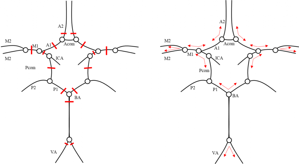
| Abbreviation/key | Instructions |
| A2 | A2 segment of the anterior cerebral artery (left and right) at 5 mm beyond the anterior communicating artery |
| A1 | A1 segment of the anterior cerebral artery (left and right) at 50% of the total artery length |
| M1 | M1 segment of the middle cerebral artery (left and right) at 50% of the total artery length |
| P1 | P1 segment of the posterior cerebral artery (left and right) at 5 mm beyond the basilar artery top |
| Pcom | posterior communicating artery (left and right) at 50% of the total artery length |
| ICA | internal carotid artery (left and right) at 5 mm below its top |
| VA | vertebral artery (left and right) at 5 mm below the vertebrobasilar junction |
| BA | basilar artery at 5 mm below its top |
Angle annotation protocol
Artery centerlines were extracted using the output of a pre-trained 3D U-Net for artery segmentation2 followed by skeletonization3. The annotator was asked to select the two arteries forming the desired bifurcation angle. Angles were computed using the vector directions that originate from the point where the centerlines of both arteries intersect. The geodesic distance from the intersection was set at ~5 mm.
| Abbreviation/key | Instructions |
| A2/A1 | bifurcation between the A1 and A2 segment of the anterior cerebral artery (left and right). This was taken at the position of the anterior communicating artery. In case of hypoplasia or aplasia, the angle was computed at the point of largest curvature. |
| ICA top | bifurcation at the top of the internal carotid artery (left and right) |
| M2/M2 | bifurcation between the M2 segments of the middle cerebral artery (left and right) |
| Pcom/C7 | bifurcation between the posterior communicating artery and the C7 (terminal communicating) segment of the internal carotid artery (left and right) |
| VBJ | bifurcation between the vertebral basilar arteries, at the vertebrobasilar junction |
| BA top | bifurcation at the top of the basilar |
References
1. Vos, I. N., et al. “Assessment of manual and automated intracranial artery diameter measurements.” Medical Imaging 2022: Image Perception, Observer Performance, and Technology Assessment. Vol. 12035. SPIE, 2022.
2. de Vos, V., et al. “Automatic cerebral vessel extraction in TOF-MRA using deep learning.” arXiv preprint arXiv:2101.09253 (2021).
3. Selle, D., Preim, B., Schenk, A., and Peitgen, H.-O., \Analysis of vasculature for liver surgical planning,”
IEEE transactions on medical imaging 21(11), 1344{1357 (2002).